Me neither!
Monday, October 5, 2009
Sunday, October 4, 2009
The Cost
I like to keep a running tally of costs associated with these projects (so my wife doesn't have a heart attack hahaha).
Cabinet:
Cabinet:
- Cabinet and coin door: $36 (I still can't believe it)
- Zinsser BIN primer (1 gallon): $20 from Home Depot
- Blue paint (1 gallon): $45 from Sherwin Williams (way expensive, but worth it)
- Black paint (1 quart - Rustoleum semi-gloss): $8 from Home Depot
- Bondo: $12 from Home Depot
- Rubber feet: $2 from Home Depot
- Control panel overlay: $30 from eBay
- Control panel instruction card underlay: $5 from Arcade Shop
- Button set for Nintendo Classic control panels: $15 from MikesArcade.com
- Nintendo Control Panel bolt set (8 bolts/nuts): $10 from MikesArcade.com
- 3 Nintendo button holders (with microswitches): $28 from MikesArcade.com
- Nintendo CP Strike Set: $5 from MikesArcade.com
- Joystick (Sanwa JLF) and harness: $35 from lizardlick.com
- 1/16" ABS plastic (24" x 24"): $17 from eBay
- 1/2" MDF panel: $0 (on hand)
- Marquee: $40 from Arcade Shop
- Side Art: $65 from QuarterArcade
- Bezel: $45 from Arcade Shop.com
- Bezel instruction card decal: $5 from Arcade Shop
- Nintendo coin door decals: $6 from ThisOldGame
- Light: $12 from Home Deopt
- Marquee/bezel retainers: $17 from MikesArcade.com
- 9/16" t-molding: $10 from Arcade Shop
- 19" Tri-Res CGA/EGA/VGA monitor: $239+$28 S/H from Arcade Shop
- Computer/PCB
- Powdercoating coin door: $75 from local shop
- Asahi Seiko Coin Mechs (2): $76 factory direct
Saturday, September 26, 2009
Nintendo Serial Plate
When Nintendo originally manufactured their arcade cabinets, each one was given a unique model number stamped onto a serial plate which was screwed to the back of the cabinet right above the removable panel. Unfortunately, my cabinet did not come with one but leapinlew over at BYOAC told me he had an extra and he was kind enough to send it to me for FREE! Thanks buddy! Check it out:


 For those that may be wondering, the serial plate measures 4" x 1-7/8" and is held in place by 4 small screws. Anyway, it's not a huge deal but this does add to the authenticity of the cabinet (at least to me) even though sharp eyes will notice that this particular serial plate came off of an original Popeye machine (based on the model number). It also appears to be a blank since there is no actual serial number listed. Maybe I'll stamp it with a #000001!


 For those that may be wondering, the serial plate measures 4" x 1-7/8" and is held in place by 4 small screws. Anyway, it's not a huge deal but this does add to the authenticity of the cabinet (at least to me) even though sharp eyes will notice that this particular serial plate came off of an original Popeye machine (based on the model number). It also appears to be a blank since there is no actual serial number listed. Maybe I'll stamp it with a #000001!
Tuesday, September 15, 2009
It's Alive!!
Now the moment I've been waiting for - powering it on for the first time (and praying everything works!).
It did!
 Here are some shots with the lights off - it is impossible to get a good picture but you get the idea. The marquee really pops and everything looks better than I imagined it.

 I am VERY happy with the results. I still have a few very minor things left to do (software tweaking mostly and I also have to figure out a back door even though you can't see it) but this project is about 99% finished.
I'll post a video of it working when I get a chance and other miscellaneous stuff when it pops into my head.
It did!
 Here are some shots with the lights off - it is impossible to get a good picture but you get the idea. The marquee really pops and everything looks better than I imagined it.
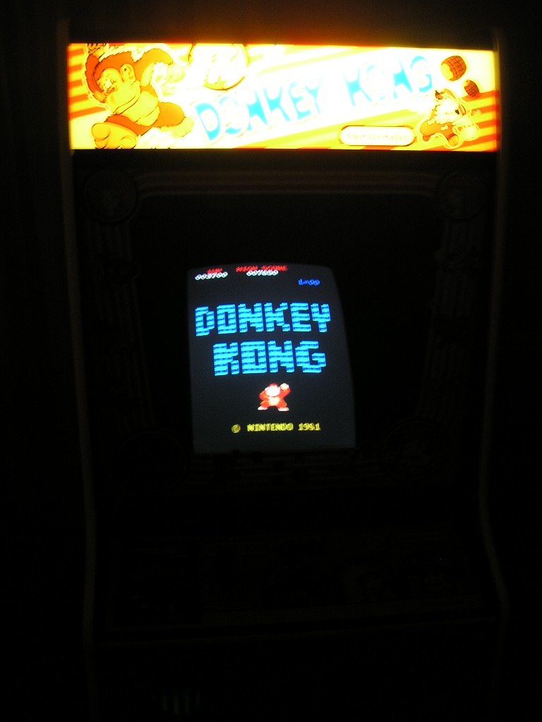
 I am VERY happy with the results. I still have a few very minor things left to do (software tweaking mostly and I also have to figure out a back door even though you can't see it) but this project is about 99% finished.
I'll post a video of it working when I get a chance and other miscellaneous stuff when it pops into my head.
Tuesday, September 8, 2009
The Brains: Part 2
Next up was installing the computer - pretty easy stuff. I just placed it on a shelf that spans the two plywood supports as shown below.

 Next, I screwed the motherboard to the shelf and then plugged everything in (hard drive, monitor, USB connections for the iPac, etc.). I don't have any pictures of this but it is pretty self-explanatory if you've made it this far.

 Next, I screwed the motherboard to the shelf and then plugged everything in (hard drive, monitor, USB connections for the iPac, etc.). I don't have any pictures of this but it is pretty self-explanatory if you've made it this far.
Monday, September 7, 2009
The Brains
Next up was getting all of the electrical components positioned and hooked up inside of this thing. First up was the SmartStrip. This is a "smart" powerstrip in that it can be set up to turn on a bunch of components when the one "hot" component is powered up. You plug the computer's main power cord into the "hot" outlet and everything else into the "switched" outlets. When the computer is turned on the monitor, marquee light and the speakers all turn on as well. It works great.
I decided to mount the SmartStrip on the side of the cabinet like this:
 I had to raise it a little so the plug from the marquee light would reach an outlet on the SmartStrip. The plug of the SmartStrip will go out the back of the cabinet and into the wall just like in an original Donkey Kong machine.
Saturday, September 5, 2009
Wiring The Controls
The next thing I had to do was wire up the control panel. I'm using an ipac keyboard encoder to connect the buttons to the computer (the green thing on the left). I used some computer "feet" to secure the ipac in place underneath the control panel.
 The ipac plugs into the computer via a USB cable and the microswitches on the buttons are wired to the nodes on the ipac. Everything is clearly labeled on the ipac and the default settings were perfect for my needs. The black wires are form the "COM" (common) pin on the microswitches and they are all daisy chained together (from button to button and into the ipac). The red wires are from the "NO" (normally open) pin on the microswitches and each one is individually wired to the ipac (to the default node on the ipac that corresponds to what I want the button to do).
 The wiring from the hidden admin buttons was done the exact same way and you can see one of the microswitches in the top of the picture that I hooked up after the control panel was in place (by reaching through the coin door and placing the microswitch in the button - blind!).
 This whole process couldn't be any easier! When I first started building these cabinets the wiring was the part that I was most intimidated by but it really is a snap.
More later.
Friday, September 4, 2009
Some More Side Art Pics
OK, time for some good pics! Here are some shots of the cab with the side art and bezel installed. I also put the computer inside and wired everything up (which I will detail in future posts). It's about 95% finished. The only thing left cosmetically is the decal above the CP on the black bar otherwise what you see is what you get.
Here's the punch list:
- laminate front bar above CP
- apply decal on front bar above CP
- remake back door (I made one already but it could be MUCH lighter)
- streamline computer boot-up
- figure out CabVol or some other volume app
- disable pop-up boxes (when I first boot, Mala loads and goes straight to DK but after I exit MaLa is no longer the top window and I need a mouse click to get it to respond again and it works fine from then on - annoying)
- Re-skin MaLa - I'm using the one from John's Arcade, which is great (I love the Games Played counter) but I want to tweak it a little and I have no idea how
- I also might make the black posterboard bezel to go around the monitor but honestly it is so dark in there it isn't necessary at all so I may skip it
That's it (I think). Anyway, check out the pics. It's pretty sweet.
Enjoy!


 I really love the way this has come together. It looks and plays exactly like a real Donkey Kong machine and it has 29 other classic games available to play. I'll post the gamelist eventually (I'm constantly tweaking it but I'm pretty settled on it for now).
More later!
Enjoy!


 I really love the way this has come together. It looks and plays exactly like a real Donkey Kong machine and it has 29 other classic games available to play. I'll post the gamelist eventually (I'm constantly tweaking it but I'm pretty settled on it for now).
More later!
Friday, August 28, 2009
The Side Art
OK, finally. I got the side art on. It was pretty easy actually once I figured out how to line it up. I felt like a genius when it finally clicked but I'm sure it is an obvious solution.
 The first thing I did was put a piece of tape 2-3/4" from the top - no need to be precise here - just make sure that the piece of tape covers the imaginary horizontal line 2-3/4" from the top of the cabinet. Then, using a carpenter's square (pictured) to get a straight line I marked the line in pencil on the tape. This gave me the line to place the top edge of the side art on. I repeated this process along the back edge of the cabinet (2-3/4" again) and now had a vertical line to place the left edge of the side art on (or right edge depending which side you are doing).
In order to use the carpenter's square properly you set the short edge of the ruler in the picture to 2-3/4". Then you place the black handle on the top edge of the cabinet so that the short edge of the ruler is hanging down exactly 2-3/4". Next you place your pencil on the bottom of the ruler's edge and run the carpenter's square along the top while moving the pencil at the same time. This will give you a perfectly straight line exactly 2-3/4" from the top (on the masking tape!). This is an invaluable trick for building things and laying out lines in general.
Now that I knew exactly where to place the side art, I just taped it to the side.
 Next, I removed all of the tape near the top and peeled off the paper backing from the sticker and cut it away with the scissors.
 Then, very carefully and using my vinyl squeegee, I applied pressure to the top portion of the decal where I removed the paper backing. No turning back now! The decal is in place!
Then, I removed all of the masking tape around the edges now that it can hang on it's own. Finally, I removed the rest of the paper backing starting at the top and working my way down with the squeegee and pressing the decal into place.
 After the decal was applied the only thing left to do was remove the top layer of paper. This part took a long time - the paper did not come off easy and in fact during this process there was a tendency to remove the actual decal form the force of removing the top layer of paper. I think this was due to my own inexperience - I did not prep the surface before applying the sticker and I should have used some rubbing alcohol to really clean it and remove any oils that may have been present.
Anyway, it came out great:
 I didn't take as many pictures as I would have liked because my hands were tied and I was a little nervous. It was actually very easy! I can really see the finish line now.
More later.
Thursday, August 27, 2009
The Coin Decal!!
Finally - the moment everyone has been waiting for is here. I applied the coin door decal to the front of the control panel!! Before attempting this, I bought a plastic squeegee off of eBay for $3 (search "vinyl squeegee") - this really helps in applying the decals and it eliminates any air bubbles.
 The first thing I did was put a piece of masking tape in the center of the panel. The tape lets me draw on the cab lightly with a pencil without leaving a mark. It makes it really easy to line up the decal. The decal is centered and the top edge of the decal is 2-1/4" from the top of the panel.
 Next, I peeled the back of the decal off just a little along the top to expose the sticky surface and cut the back off with some scissors. This allowed me to line up the decal and stick the top down. Then using the vinyl squeegee from top to bottom while removing the rest of the paper backing I pressed the decal into place.
 Looking good - all that's left is to peel away the top layer of paper. Man, you should have seen the smile on my face as I was peeling this off.

 It looks pretty sweet! Next up will be the side art - it's actually the same process just on a much larger scale and way more nerve-wracking!
More later.
 The first thing I did was put a piece of masking tape in the center of the panel. The tape lets me draw on the cab lightly with a pencil without leaving a mark. It makes it really easy to line up the decal. The decal is centered and the top edge of the decal is 2-1/4" from the top of the panel.
 Next, I peeled the back of the decal off just a little along the top to expose the sticky surface and cut the back off with some scissors. This allowed me to line up the decal and stick the top down. Then using the vinyl squeegee from top to bottom while removing the rest of the paper backing I pressed the decal into place.
 Looking good - all that's left is to peel away the top layer of paper. Man, you should have seen the smile on my face as I was peeling this off.
 It looks pretty sweet! Next up will be the side art - it's actually the same process just on a much larger scale and way more nerve-wracking!
More later.
Thursday, August 20, 2009
The Coin Door: Part 3
Well, here it is - all installed and looking brand new:

 Next up - installing the side art and other random stuff!

 Next up - installing the side art and other random stuff!
The Coin Door: Part 2
In addition to having the door powder coated, I also ordered two brand new coin mechs from Asahi Seiko in Las Vegas (they still make them!) so the entire thing now looks factory fresh. It was EXPENSIVE ($93 for the new mechs!). Here is what the old mechs looked like - these were unfixable to me with the rust and everything (not so much on the outside but around the coin return button):
 It took about a week for the new mechs to arrive but it was worth the wait. Here's some unboxing pictures for the full effect:


 They look great. Next up - final installed coin door pics!
 It took about a week for the new mechs to arrive but it was worth the wait. Here's some unboxing pictures for the full effect:


 They look great. Next up - final installed coin door pics!
The Coin Door
The coin door is the one thing I didn't feel comfortable restoring myself. I could have taken a can of spray paint to it but I didn't want to risk ruining it. As far as I know there aren't any vendors out there selling Nintendo coin door reproductions which means there is a finite number of these things out there to be had. I was lucky - mine came with the cabinet and was in pretty good shape. No major dents or scratches.


 As you can see the door had started to rust in several spots and the paint was bubbling all over the place. A local custom motorcycle shop has powdercoating capabilities so had them refinish it for me (as well as the bottom marquee retainer). It came out very nice and way better than if I had attempted to do this myself.
I ordered some #6-32 carriage bolts from Quarter Arcade to secure the door to the cabinet and they fit perfectly. I had to order 2 sets though since I needed 12 for the door and they only sold them in packs of 10. I also bought a $4 lock from Home Depot which fit perfectly. Here's what it looks like installed:
 I'm not sure why - maybe it was the lighting or the sweet finish on the door - but I can't seem to get a good picture of it. The door looks brand new and I couldn't be happier with the result.
More later.
Tuesday, August 18, 2009
The Monitor Mount: Part 5
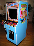
Now that the monitor is in place I guess I can show off what it looks like from the front!

 It looks great! I'm hoping the monitor is at a suitable viewing angle - since I didn't have anything but pictures to go off of it was tough positioning it just right. Seems OK to me...
More later!

 It looks great! I'm hoping the monitor is at a suitable viewing angle - since I didn't have anything but pictures to go off of it was tough positioning it just right. Seems OK to me...
More later!
The Monitor Mount: Part 4
There was one more small problem after getting everything ready for the monitor - since we removed those triangular mounting brackets that came with the monitor, the electronics which operate everything were loose and hanging by the connecting wires - not good. This is actually where my mother came in very handy. Every time my father and I lifted the monitor to move it around she had to hold the electronics so there was no tension on any wires - not easy - it was like a game of Twister or something. Thanks mom!
Once the frame was ready, we slid the monitor into its final resting position and stood there holding the electronics. We were tired at this point and I made the executive decision to just screw the panel into the 2x4s with two 3" screws. It worked great. The electronics are at an angle inside of the cabinet but there is no tension in any of the wires:

 You can see the screw in the upper corner going right through the metal - there is another on the opposite corner and it is very secure. Here are some more shots from behind showing how the monitor is mounted inside of the cabinet:


 I don't know if you can tell but this was by far the toughest part of the project. We spent 2 full days getting this thing in place just right. I'm glad that's over!
More later.
Once the frame was ready, we slid the monitor into its final resting position and stood there holding the electronics. We were tired at this point and I made the executive decision to just screw the panel into the 2x4s with two 3" screws. It worked great. The electronics are at an angle inside of the cabinet but there is no tension in any of the wires:

 You can see the screw in the upper corner going right through the metal - there is another on the opposite corner and it is very secure. Here are some more shots from behind showing how the monitor is mounted inside of the cabinet:

 I don't know if you can tell but this was by far the toughest part of the project. We spent 2 full days getting this thing in place just right. I'm glad that's over!
More later.
The Monitor Mount: Part 3
After getting the monitor into the frame I had to figure out a way to support the frame from the inside of the cabinet at the proper angle and not drill into the side panels. I had my dad slide the MDF panel with the monitor into place (the Donkey Kong cabinet had a mounting bracket for the original monitor still in there so he rested it on there):
 Once I thought it was at a good viewing angle we drew a line underneath the panel on both sides which represented the spot where we wanted the panel to sit. All we had to do was build some legs for it. We ended up using some 2x4s to build a frame - imagine a table with 4 legs and cross braces except the table top is set at a sever angle. That's all there was to it but coming up with the design was far easier than actually building it. I don't know why but getting all of the measurements just right really took a long time. This is what we ended up with:

 The MDF panel holding the monitor would sit on top of the 2x4 frame - all done! Well, not quite... In our infinite wisdom, we didn't take into consideration the weight of the monitor. We lifted the monitor and slid it in place expecting everything to be perfect (tight fit, eh?):
 The problem was since there was nothing actually holding the frame to the cabinet, gravity wanted to force the entire structure, monitor and all, out the back of the cabinet. We felt like idiots for not thinking of this sooner. We were running out of time in the day (a Sunday) and we couldn't leave the exposed monitor in the MDF - we had to figure this out!
After brainstorming for about an hour the solution finally presented itself. I had some spare angle brackets lying around from when I mounted the new base to the bottom of the cabinet. The support pieces we cut for the top of the frame just happened to be long enough to almost touch the plywood where the original mounting bracket was located. We installed a bunch of angle brackets using bolts (not screws) which prevented the frame from tipping backwards and moving at all.

 We were so happy this ended up working without seriously modifying the back of the cabinet (which is what most of our ideas centered around).
More later.
 Once I thought it was at a good viewing angle we drew a line underneath the panel on both sides which represented the spot where we wanted the panel to sit. All we had to do was build some legs for it. We ended up using some 2x4s to build a frame - imagine a table with 4 legs and cross braces except the table top is set at a sever angle. That's all there was to it but coming up with the design was far easier than actually building it. I don't know why but getting all of the measurements just right really took a long time. This is what we ended up with:
 The MDF panel holding the monitor would sit on top of the 2x4 frame - all done! Well, not quite... In our infinite wisdom, we didn't take into consideration the weight of the monitor. We lifted the monitor and slid it in place expecting everything to be perfect (tight fit, eh?):
 The problem was since there was nothing actually holding the frame to the cabinet, gravity wanted to force the entire structure, monitor and all, out the back of the cabinet. We felt like idiots for not thinking of this sooner. We were running out of time in the day (a Sunday) and we couldn't leave the exposed monitor in the MDF - we had to figure this out!
After brainstorming for about an hour the solution finally presented itself. I had some spare angle brackets lying around from when I mounted the new base to the bottom of the cabinet. The support pieces we cut for the top of the frame just happened to be long enough to almost touch the plywood where the original mounting bracket was located. We installed a bunch of angle brackets using bolts (not screws) which prevented the frame from tipping backwards and moving at all.

 We were so happy this ended up working without seriously modifying the back of the cabinet (which is what most of our ideas centered around).
More later.
Subscribe to:
Posts (Atom)